


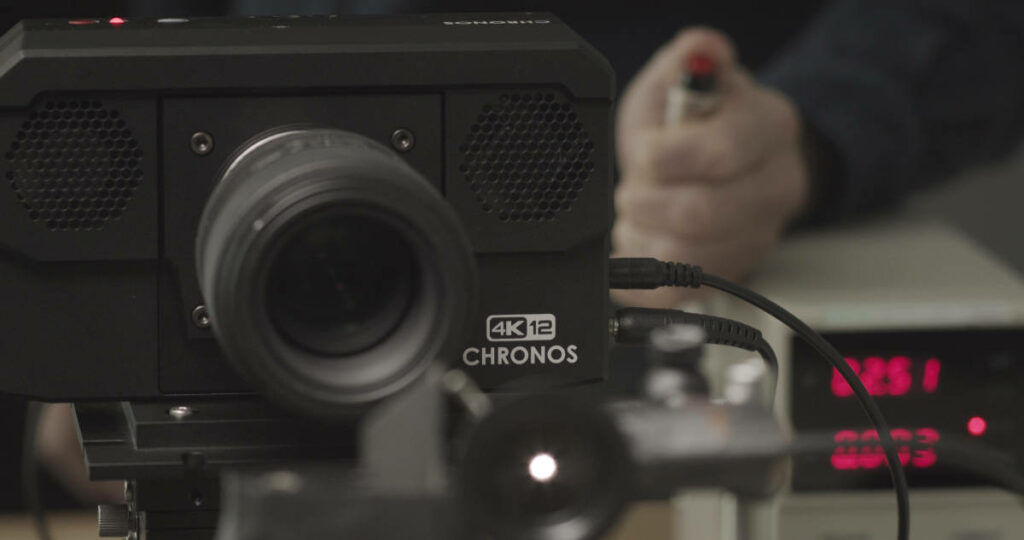
Precision Redefined: Real-time DIC with Mercury RT and Chronos Cameras
Breaking New Ground with Mercury MS S.r.o. We’re thrilled to announce a new partnership between Kron Technologies…
Chronos highspeed camera systems offer the portability, ease-of-use, and video quality required by Universities and R&D Labs to understand Schlieren Imaging in-depth.
Schlieren Imaging is a technique that allows us to see the subtle changes in the refractive index of fluids. It can reveal the flow of air, temperature variations, and shockwaves that are otherwise invisible to the naked eye.
High-speed cameras coupled with a Schlieren visualization setup can capture rapid changes in air density or temperature that are not visible by the naked eye. With Chronos High-Speed Cameras, unlock the intricacies of Schlieren Imaging processes and get ready for detailed analysis and visualizations, all with unparalleled efficiency.


Image 2. Images showing a candle being blown by the air from a heat gun. The video was captured with the new Chronos 4K12 camera. Image size 3840 X 2160, video recorded at 937 fps 8-bit.

Image 3. The initial hot air from from a heat gun. The images were also captured. Similar to image 2, the video was captured with the new Chronos 4K12 camera. Image size and frame rate are the same.
In a uniform medium, light travels without deviation. However, when the medium is disrupted by changes in pressure or temperature, its density fluctuates, altering its refractive index. As a result, a beam of light passing through this changing density can no longer follow a straight path; it bends and twists. Enter the “knife-edge,” a thin, rigid object strategically placed in the light’s path. It filters out the unaffected rays, allowing only those bent by the changing medium density to create the captivating images you’ll see on your screen.

Figure 1. Schematic diagram of the Schlieren Imaging setup
The following list shows the different elements in the Kron Technologies’ Schlieren setup. The test rig was used to capture high-speed videos and the images presented at Krontech.ca. The list can serve as a guide for those interested in building a Schlieren imaging setup.
The essential items are the parabolic mirror, the light source, the camera and the knife edge. Other elements are included as well. Feel free to look for other alternatives that allow you to build your Schlieren system in a more cost effective way.
The LED source used, DigiKey product number SST-20-W40H-A120-J5402, is no longer manufactured. Please refer for a similar item at DigiKey.com
The different elements used for the Schlieren setup, except the spherical mirror, were mounted on a breadboard. The camera and the knife edge were mounted each on an XY-axis stage for precise placement.
There were also other optomechanical components used. They were purchased at Thorlabs.com.
The XY-stages contain 4mm thread holes while the breadboard has 6mm thread holes. To connect these two components a couple of plates were designed. One was to join the breadboard and the XY-stage. One more plate was used to couple the upper surface of the XY-stage to the optical components.
Feel free to download the files below and make the connecting plates yourself or have them made at the machine shop of your preference.
*Step can be accessed through Intercom
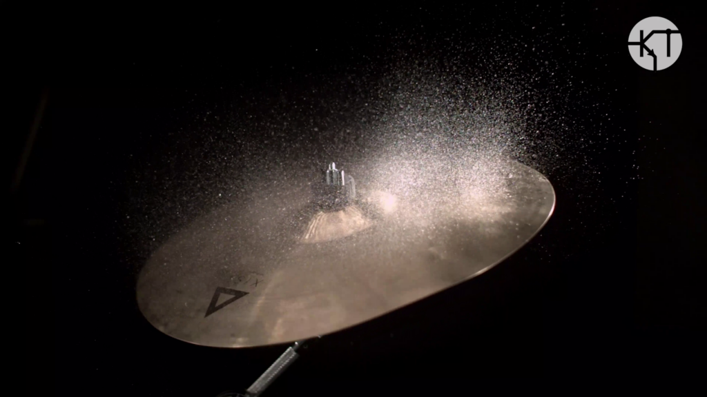
Some things to consider when choosing a high-speed camera for Schlieren Imaging:

Breaking New Ground with Mercury MS S.r.o. We’re thrilled to announce a new partnership between Kron Technologies…
Droplets deposited on a sufficiently hot surface experience an interesting phenomenon. They skid on a layer of…
Discover the power of Chronos high-speed cameras, designed to meet the demands of content creators and videographers.
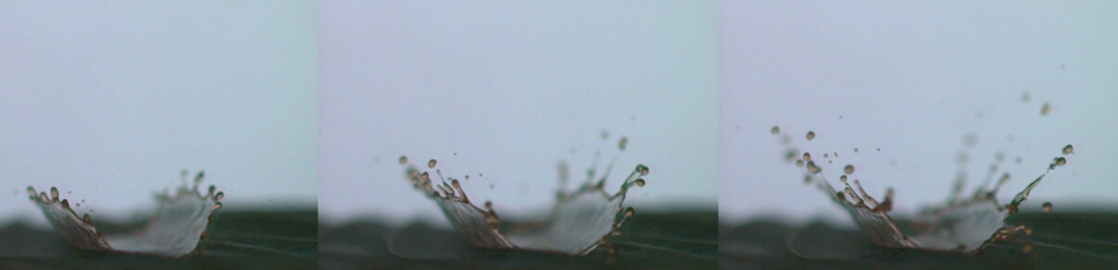
Brief history of droplet impact The study of droplet impact can be traced back to the nineteenth…

In this article, we’d like to discuss another interesting topic: computational fluid dynamics, also referred to as...

Fluid mechanics describes the flow of fluid whether at rest or in motion1. The surface of the…